DIY Electronics
Simple electronics as a hobby
Explanation of 15 small electronic circuits
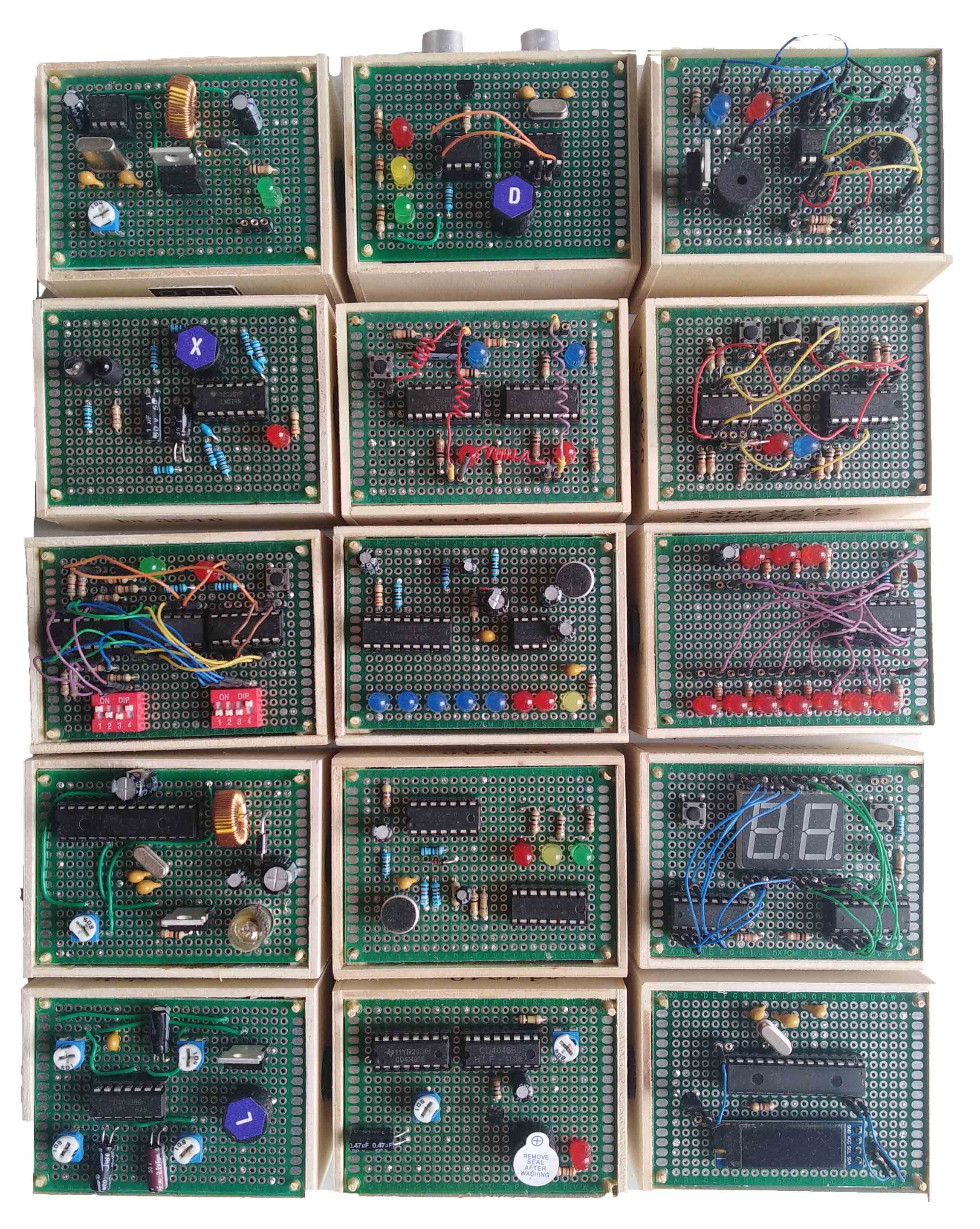 From top left to bottom right.
a. DC boost converter
b. Park assist
c. Astable multivibrator 555 timer
d. Heart rate sensor
e. JK flip flops
f. 1 bit full adder
g. Key code comparator
H. VU meter
i. Oscillator
j. DC boost converter with load
k. Clap switch
l. 7-segments counter
m. Quad oscillator
n. Tone burst generator
o. Ultrasonic distance measurement
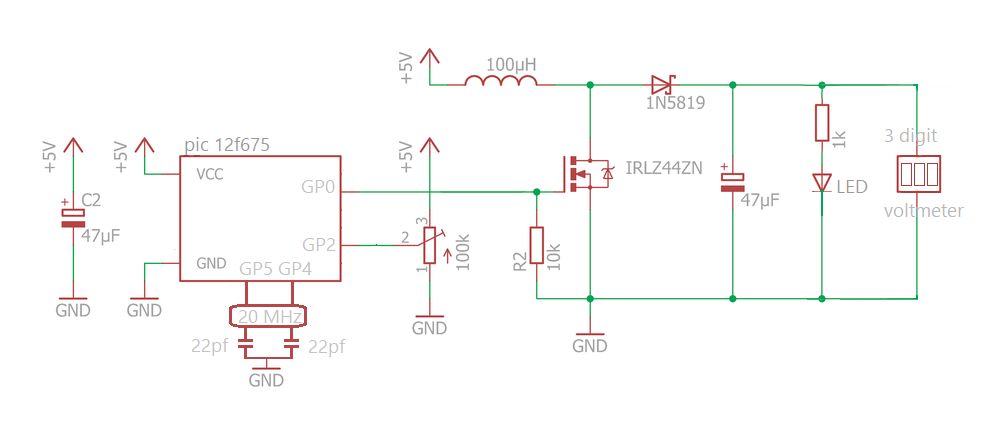
a. DC boost converter
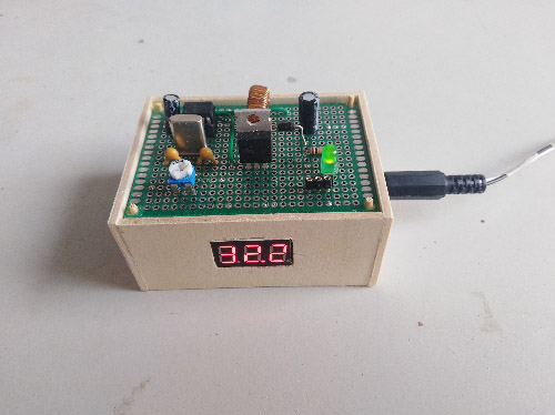 This circuit uses a IRLZ44N instead of an IRFZ44N mosfet.
The low gate threshold voltage of the IRLZ44N makes it easier to drive the MOSFET from a microcontroller's PWM output, which typically has a voltage range of 0-5V. The low on-state resistance of the IRLZ44N also means that it can handle higher currents without dissipating too much power, which is important for fast PWM applications (chatGPT).
This circuit uses a IRLZ44N instead of an IRFZ44N mosfet.
The low gate threshold voltage of the IRLZ44N makes it easier to drive the MOSFET from a microcontroller's PWM output, which typically has a voltage range of 0-5V. The low on-state resistance of the IRLZ44N also means that it can handle higher currents without dissipating too much power, which is important for fast PWM applications (chatGPT).This circuit has no feedback circuit to change the duty cycle when the load changes.
With a minimal load the circuit boost 5 volts to more than 30 volts.
 >>> Pic12f675 code (XC8 compiler) for boost converter <<<
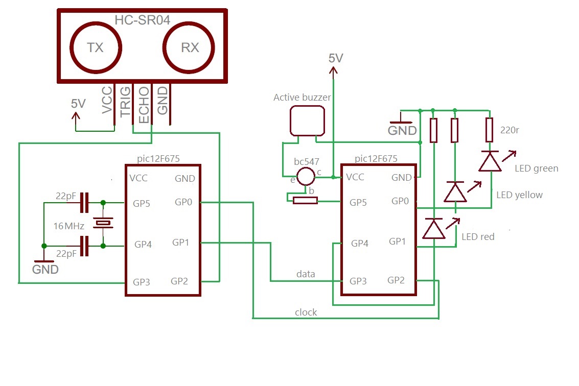
b. Park assist
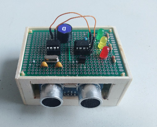 With the ultrasonic sensor distance is measured. When the software pulls the trigger pin high
for 10 microseconds the sensor sends 8
pulses of 40KHz and it pulls up the echo pin, indicating a timer should be started.
When the echo pin goes low, the timer should be stopped.
With the ultrasonic sensor distance is measured. When the software pulls the trigger pin high
for 10 microseconds the sensor sends 8
pulses of 40KHz and it pulls up the echo pin, indicating a timer should be started.
When the echo pin goes low, the timer should be stopped.End time minus start time multiplied by the speed of sound divided by two (round trip) gives you the distance. Speed of sound is 0.0343 cm/us (cm per micro-seconds) at 20 Celcius or 0.0350 cm/us at 30 degrees. A shortcut is to divide the round trip time by 57 (=1/(0.350/2)). The first pic controls the sensor and calculates the distance using an interrupt on change (GP3) to start and stop timer1. The second chip gives warning light and sound and continues to do so even when the first pic recalculates the distance. Both chips communicate using a clock and data line.
When the clock is set high (rising edge) the second chip generates an interrupt on GP2 and examens the data line.
 >>> Pic12f675 code (XC8 compiler) for ultrasonic sensor <<<
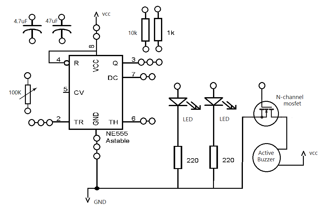
c. Astable multivibrator
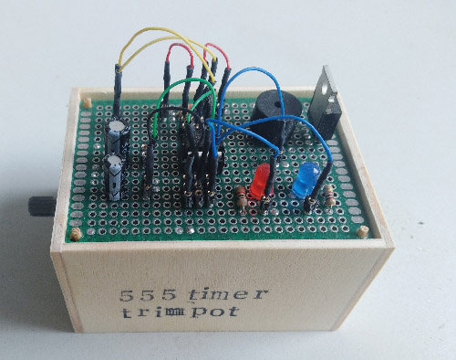 Astable multivibrator with a 555 timer. With female headers and tiny dupont cables it becomes a game to
make the right connections and play with the resistor, capacitor values and trimpot.
Astable multivibrator with a 555 timer. With female headers and tiny dupont cables it becomes a game to
make the right connections and play with the resistor, capacitor values and trimpot.
d. Heart rate sensor
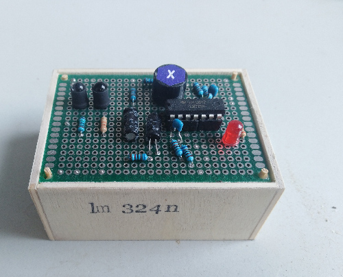 This circuit measures the heart rate through a fingertip. While the heart is beating, the blood volume inside the finger artery changes too.
This fluctuation of blood can be detected by a pair of IR transmitter and IR receiver.
The weak signal (pulse) has to be amplified and filtered.
This circuit measures the heart rate through a fingertip. While the heart is beating, the blood volume inside the finger artery changes too.
This fluctuation of blood can be detected by a pair of IR transmitter and IR receiver.
The weak signal (pulse) has to be amplified and filtered.
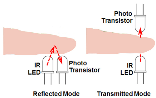 When there is more blood in the artery, there will be more hemoglobin to absorb the infrared light, resulting in less light passing through the tissue and being detected by the sensor.
The reversed biased photo diode increases conductivity when more IR light is detected.
When there is more blood in the artery, there will be more hemoglobin to absorb the infrared light, resulting in less light passing through the tissue and being detected by the sensor.
The reversed biased photo diode increases conductivity when more IR light is detected.
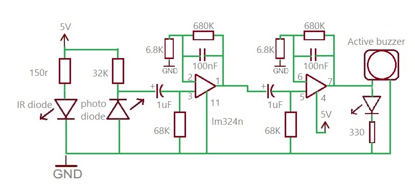 The circuit diagram above shows the IR diode (transparent) and the photo diode (dark) along with the circuit made of two stage operational amplifiers (lm324n) configured as active low pass filters. The cut-off frequencies of both the filters are set to about 2.3 Hz,
so it can measure the pulse rate up to 2.3*60 = 140 bpm. The gain of each filter is about 100, which gives the total 2-stage amplification of 10000. This is good enough to convert the weak pulsating signal into a binary pulse. At the input of each OpAmp filter stage, there is a 1 uF capacitor to block any DC component in the signal.
The circuit diagram above shows the IR diode (transparent) and the photo diode (dark) along with the circuit made of two stage operational amplifiers (lm324n) configured as active low pass filters. The cut-off frequencies of both the filters are set to about 2.3 Hz,
so it can measure the pulse rate up to 2.3*60 = 140 bpm. The gain of each filter is about 100, which gives the total 2-stage amplification of 10000. This is good enough to convert the weak pulsating signal into a binary pulse. At the input of each OpAmp filter stage, there is a 1 uF capacitor to block any DC component in the signal.
Gain of each stage is 1 + 680K/6.8K = 101
Cut off frequency is 1/2pi*680K*100nF = 1/6.28 * 680000 * 0.0000001= 2.34Hz
e. JK Flip Flops
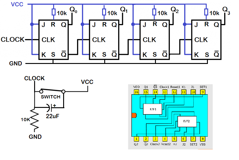
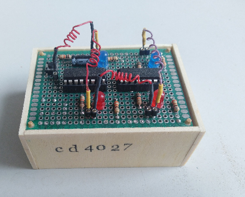 This circuit uses 2 cd4027 IC's, in total 4 JK flip flops. The ff are configured in toggle mode. When the clock goes high, Q0 goes high (first LED), the second clock pulse make Q0 low and Q bar high and that triggers the clock of the second ff, turning Q1 (second LED) high, and so on. The reset pin is tied to VCC with a 10k resistor, the set pin is tied to ground.
The switch is debounced with a capacitor of 22uF, a lower capacitance might be better, but it works.
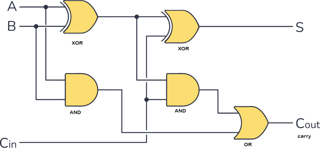
f. 1-bit full adder
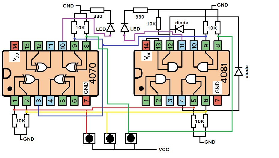
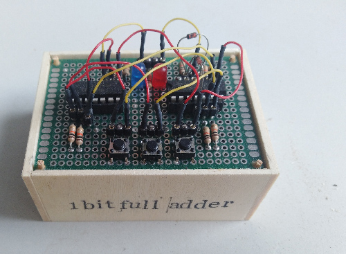 For this circuit IC cd4070 (XOR-gates) and IC cd4081 (AND-gates) are used. One AND-gate is turned into an OR-gate.
Input pins should either be kept high or low to avoid unpredictable outputs due to their high impedance. Here input pins are pulled down with 10K ohm resistors. Two diodes were needed to avoid current flowing to a low impedance output pin.
For this circuit IC cd4070 (XOR-gates) and IC cd4081 (AND-gates) are used. One AND-gate is turned into an OR-gate.
Input pins should either be kept high or low to avoid unpredictable outputs due to their high impedance. Here input pins are pulled down with 10K ohm resistors. Two diodes were needed to avoid current flowing to a low impedance output pin.
g. Key code comparator
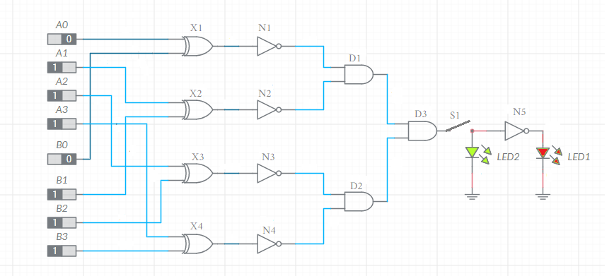
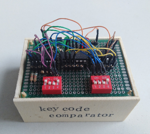 Two 4-bit numbers are compared; when equal the green LED is lit after pressing the button, otherwise the red LED lights up.
In absence of XNOR gates, XOR (cd4070) and NOT (cd4069) gates are used, together with AND(cd4081) gates.
Two 4-bit numbers are compared; when equal the green LED is lit after pressing the button, otherwise the red LED lights up.
In absence of XNOR gates, XOR (cd4070) and NOT (cd4069) gates are used, together with AND(cd4081) gates.
h. VU-meter
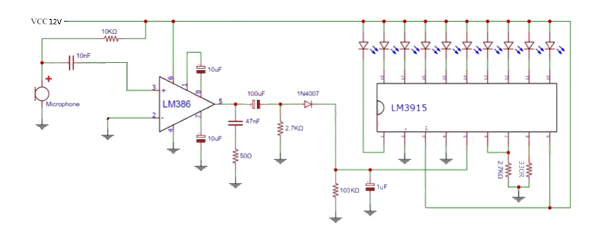
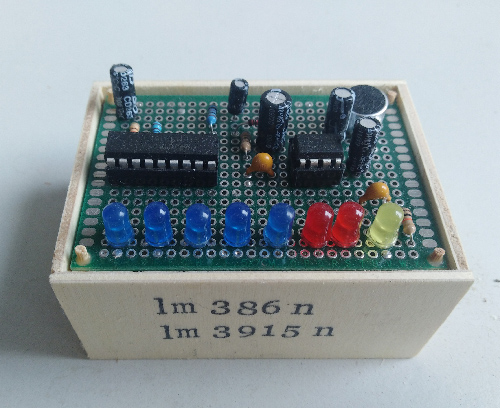 A VU meter is a device for measuring the level of sound intensity. The circuit uses a LM386N and LM3915N showing sound intensity
with the number of LEDs lighting up. Vcc of 12 volts is mandatory for a good result.
A boost converter is used to step up from 5 to 12 volt
A VU meter is a device for measuring the level of sound intensity. The circuit uses a LM386N and LM3915N showing sound intensity
with the number of LEDs lighting up. Vcc of 12 volts is mandatory for a good result.
A boost converter is used to step up from 5 to 12 voltThe function of the LM386N-1 is to amplify audio signals with low power consumption and high efficiency.
The LM3915 can drive up to 10 LEDs, which can be used to display a range of analog voltage levels. It has a built-in voltage reference and can accept signals ranging from 0V to the supply voltage. The output of the LM3915 is configured to drive a bar display (not a dot display).
i. Oscillator
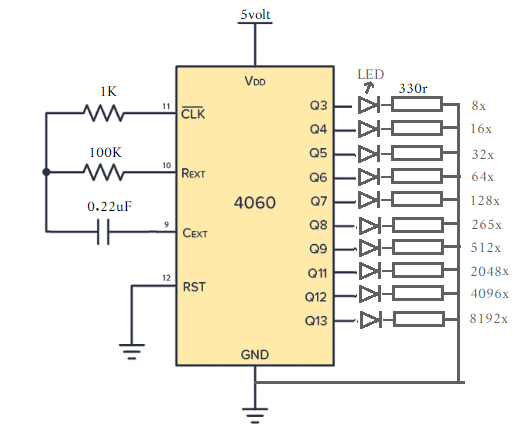
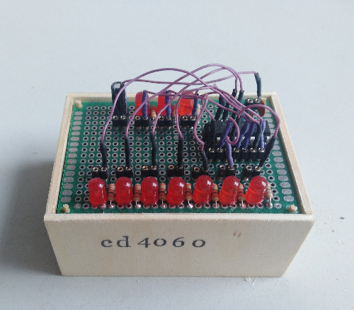 The CD4060 is a CMOS chip with a binary counter and oscillator included. It can be used to produce selectable time delays or to create signals of different frequencies. This is because it has a built-in oscillator module that only requires a few passive electronic components.
 It is also possible to use a crystal instead of an RC circuit to establish frequency.
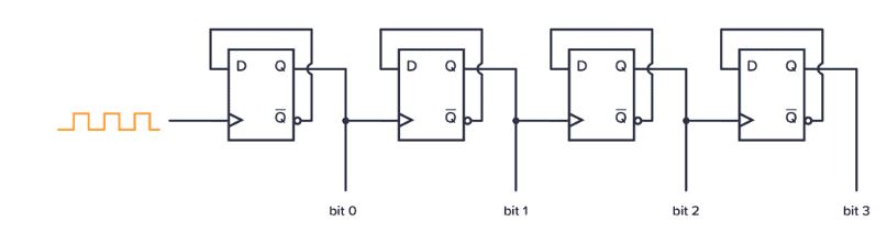 The cd4060 has 14 D-flip flops and the clock signal ripples through the flip-flops. Q3 goes high after 8 clock signals, Q4 afer 16 clock signals and so on.
Missing are Q0, Q1, Q2, and Q10.
The cd4060 has 14 D-flip flops and the clock signal ripples through the flip-flops. Q3 goes high after 8 clock signals, Q4 afer 16 clock signals and so on.
Missing are Q0, Q1, Q2, and Q10.
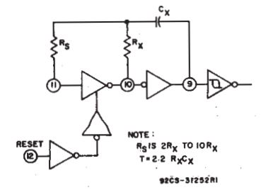 According to the datasheet the formula to calculate time is 2.2 x Rx x Cx (pin 10 and pin 9). Rs should be 2 to 10 times the value of Rx.
My circuit has the wrong resistor values to use this formula. With the 10nF capacitor the frequency of Q3 is 38.46 Hz and 1.45 Hz when connect to the 0.22 uF capacitor.
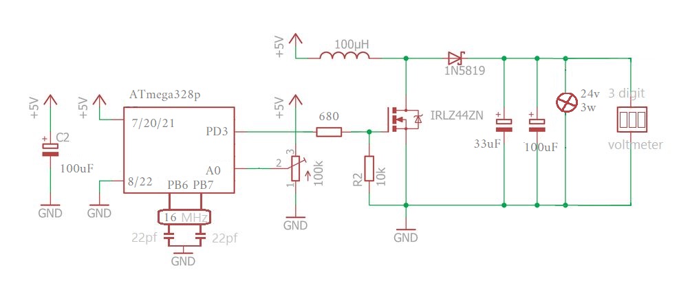
j. DC boost converter with load
 In this circuit a ATmega328p is used (Arduino UNO) and configured for fast PWM (mode 7).
It is necessary to put a resistor between output pin MCU and the MOSFET. I tried different values and 680 ohm gave the best result in a stable PWM square wave. If the duty cycle gets above 65% the square wave collapses (I don't know why). The load is a 24v 3watt light bulb and the maximum voltage turned out to be 14 volt.
 >>> Arduino UNO code for fast PWM mode 7 <<<
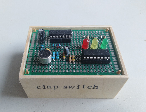 The clap switch circuit is described in detail on
 l. 7-segments counter
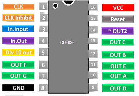
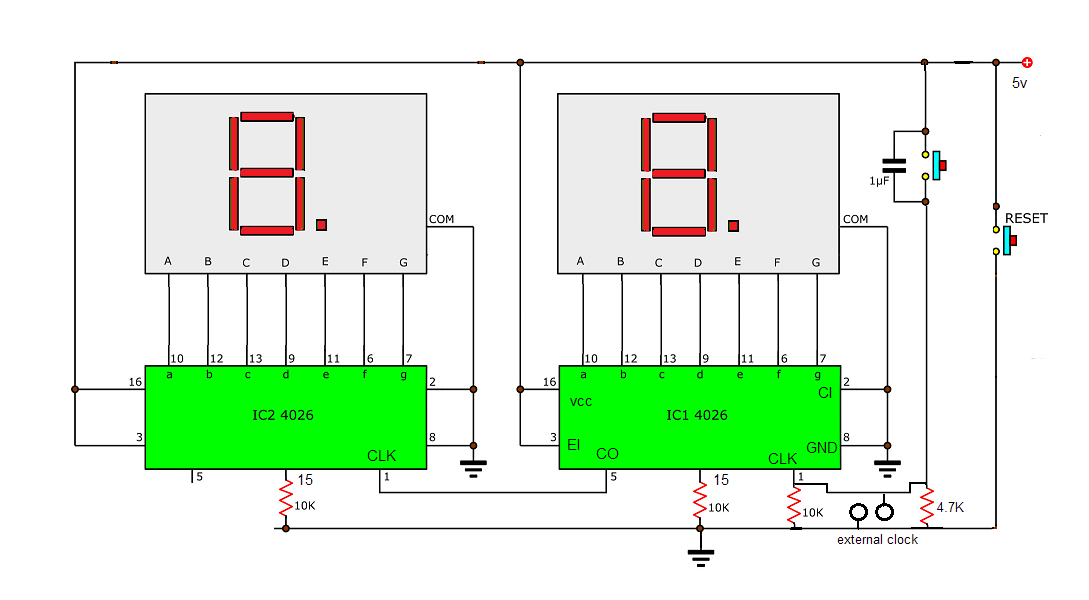
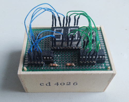 This CD4026 IC performs digital displays as it can convert input into a decimal digit which can be seen on the Common Cathode Type 7-segment display.
m. Quad oscillator
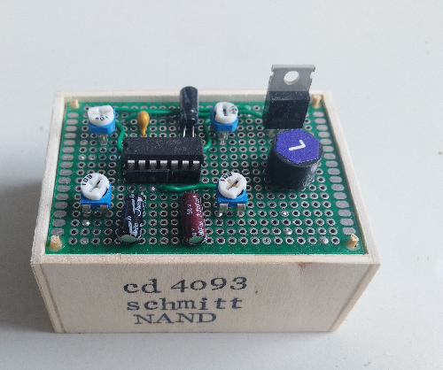 This is a Schmitt trigger NAND gate. If the input is currently LOW, then a Schmitt trigger gate might require the input voltage to go above for 3.5V to switch to HIGH. But when it has switched to HIGH, dropping a bit below 3.5V doesn’t matter. Because in order to switch back to LOW, the Schmitt trigger gate requires the input to go down below for example 1.5V.
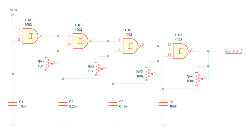
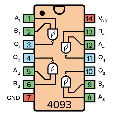 This circuit uses the four NAND gates in the chip to create four oscillators that are connected in series. Each oscillator has a capacitor and a potentiometer that you can use to adjust the frequency. This creates a old-school computer type of sound.
The first oscillator is the slowest. It turns all the others on and off at a slow speed. Then the next one is a bit faster. Then the third one is even faster. And the fourth one is the fastest.
This circuit uses the four NAND gates in the chip to create four oscillators that are connected in series. Each oscillator has a capacitor and a potentiometer that you can use to adjust the frequency. This creates a old-school computer type of sound.
The first oscillator is the slowest. It turns all the others on and off at a slow speed. Then the next one is a bit faster. Then the third one is even faster. And the fourth one is the fastest.
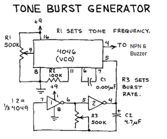
n. Tone burst generator
 This circuit comes from "The Forrest Mims Engineers Notebook", page 123. It uses a phase-locked loop IC (cd4046) of which
only the voltage controlled oscillator (VCO) is utilized and a NOT-gate (cd4049) configured as an astable multivibrator. The clock output can be regulated by the trimpot of 500K and is input (pin 5) of cd4046. CD4060 modulates the input frequency also controlled by a 500K trimpot and set output to pin 4 (burst rate).
This circuit comes from "The Forrest Mims Engineers Notebook", page 123. It uses a phase-locked loop IC (cd4046) of which
only the voltage controlled oscillator (VCO) is utilized and a NOT-gate (cd4049) configured as an astable multivibrator. The clock output can be regulated by the trimpot of 500K and is input (pin 5) of cd4046. CD4060 modulates the input frequency also controlled by a 500K trimpot and set output to pin 4 (burst rate).
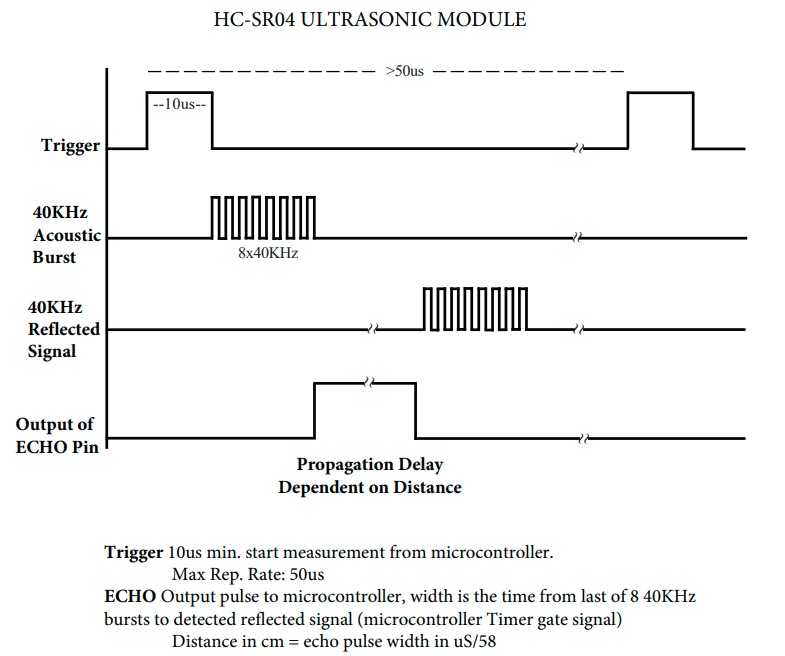
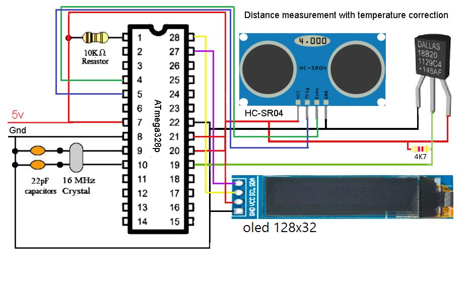
o. Ultrasonic distance measurement
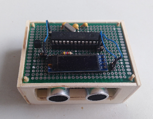 This circuit use an ATmega328p, a Dallas 18B20 temperature sensor and an OLED 128x32 display. In the timing diagram you can see
that after turning the trigger high for 10us (micro seconds). The timer should be started when the echo pin goes high and stopped
when the pin goes low (timeout after 38ms).
In the code an interrupt trigger is defined to monitor the echo pin (interrupt on change).
This circuit use an ATmega328p, a Dallas 18B20 temperature sensor and an OLED 128x32 display. In the timing diagram you can see
that after turning the trigger high for 10us (micro seconds). The timer should be started when the echo pin goes high and stopped
when the pin goes low (timeout after 38ms).
In the code an interrupt trigger is defined to monitor the echo pin (interrupt on change).
 >>> Arduino code for ultrasonic sensor and temperature <<<