DIY Electronics
Simple electronics as a hobby
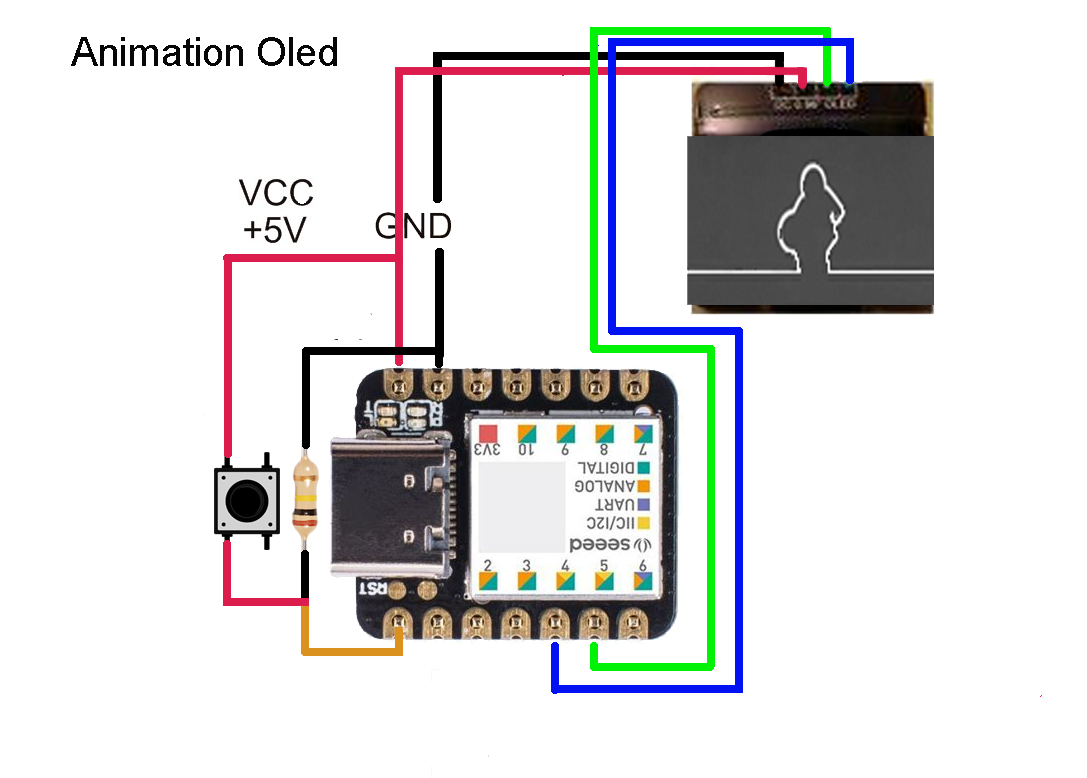
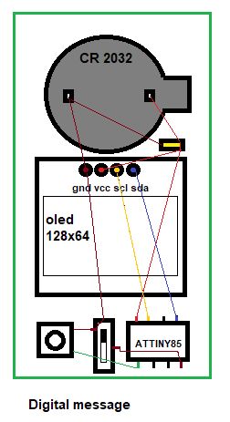
Animation using a Seeeduino xiao and Oled 128x64
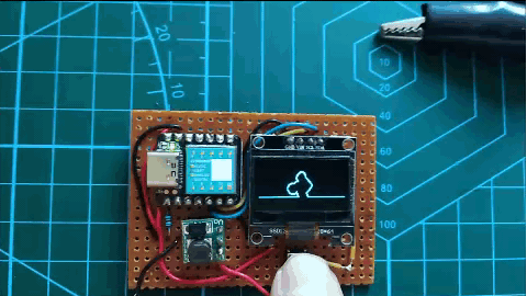 To display images on an Oled 128x64 I made 128x64 pixels BMP images with Photoshop.
The BMP file has to be converted into a hex file, readable by the microcontroller.
Every pixel is a bit. The first byte of 8-bits represents the first 8 pixels in the first row, second byte are the next pixels in the first row.
There are 16 bytes for each row (16x8=128px) and 64 bytes for each column. A c# program converts the BMP to Hex.
I added a tiny boost converter to raise the voltage from 1.5v to 5v, so it can run on a AAA battery.
To display images on an Oled 128x64 I made 128x64 pixels BMP images with Photoshop.
The BMP file has to be converted into a hex file, readable by the microcontroller.
Every pixel is a bit. The first byte of 8-bits represents the first 8 pixels in the first row, second byte are the next pixels in the first row.
There are 16 bytes for each row (16x8=128px) and 64 bytes for each column. A c# program converts the BMP to Hex.
I added a tiny boost converter to raise the voltage from 1.5v to 5v, so it can run on a AAA battery.
Source code Seeeduino Arduino IDE
source code for lalinea
source code for bboy gif
Convert BMP to Hex using c#
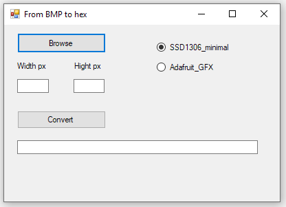 The library Attiny_minimal reads 8 pixels from top to bottom (y);
Make the image height divisable by 8.
The library Adafruit_GFX reads 8 pixels (bites) from left to right (x).
Make the image width divisable by 8.
>>> Convert BMP to Hex code <<<
Seeeduino Xiao - HID device to emulate keyboard
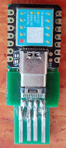 This website shows how to use seeeduino xiao with Adafruit_TinyUSb library to emulate keyboard strokes.
When seeeduino is inserted into USB port it will run the code.
The code starts "cmd" from Windows+R run box and connects to sever using FTP and uploads files, then it starts putty, connects to the server and logs in.
I put a digitalRead on pin 4 just to have a part of the code run. Pin 4 is connect to a push button to ground (not shown in the picture).
pinMode(4, INPUT_PULLUP) seems to work.
Initially I got this error when uploading the code: Adafruit_USBD_HID does not name a type; did you mean Adafruit_USBD_CDC?
The cause was two libraries with the same name Adafruit_TinyUSB_arduino; one in arduino/libraries and the other one in ..\AppData\Local\Arduino15\packages\Seeeduino\hardware\samd\1.8.5\libraries.
Then there was the return-key error. I used #define KEY_RETURN 40 to fix the problem.
Seeeduino Xiao - tryout of TM1638 model 1
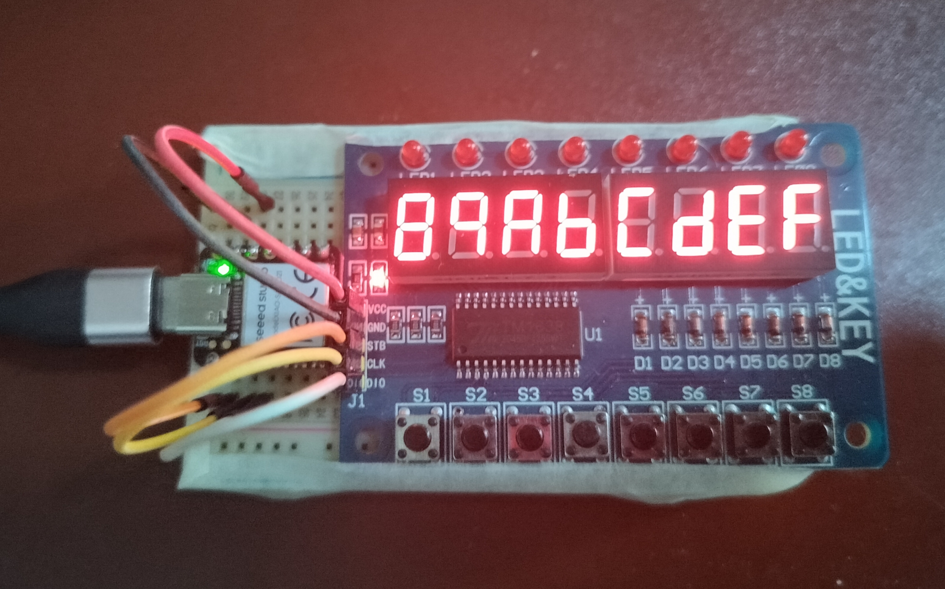 The fun part of this board is programming the seeeduino or Uno to run the tm1638 Chip and not so much the result accomplished with 8 push buttons, 8 7-segment displays and 8 LEDs.
What to know about the control pins is that to write a command to the chip the strobe line should be turned low, data is written 1 byte at the time, least significant bit first at each rising edge of the clock controlling the 8 displays or 8 leds. Arduino has a built-in function that will do just that: shiftOut(data-line, clock-line, LSBFIRST, 1-byte_of_data). When turning the strobe high again it means the end of the command, keeping it low allows data to be send, like an address or which leds of a display or single row LED to turn on/off. You can put the chip in either increment addresssing (auto advancing) or fixed addressing.
Reading button presses means sending the read command, settting pinMode to INPUT, and reading 4 bytes of data using shiftIn(data, clock, LSBFISRT). Each least significant bit of each nibble of each byte contains the status of a button push:button 1 and 5 (000x 000x first byte), button 2 and 6 (000x 000x second byte), button 3 and 7 (000x 000x third byte), button 4 and 8 (000x 000x forth byte).
Shifting bytes to the left will do the trick, the first byte << 0, second byte << 1, third byte << 2, forth byte << 3.
8 queens problem in Python
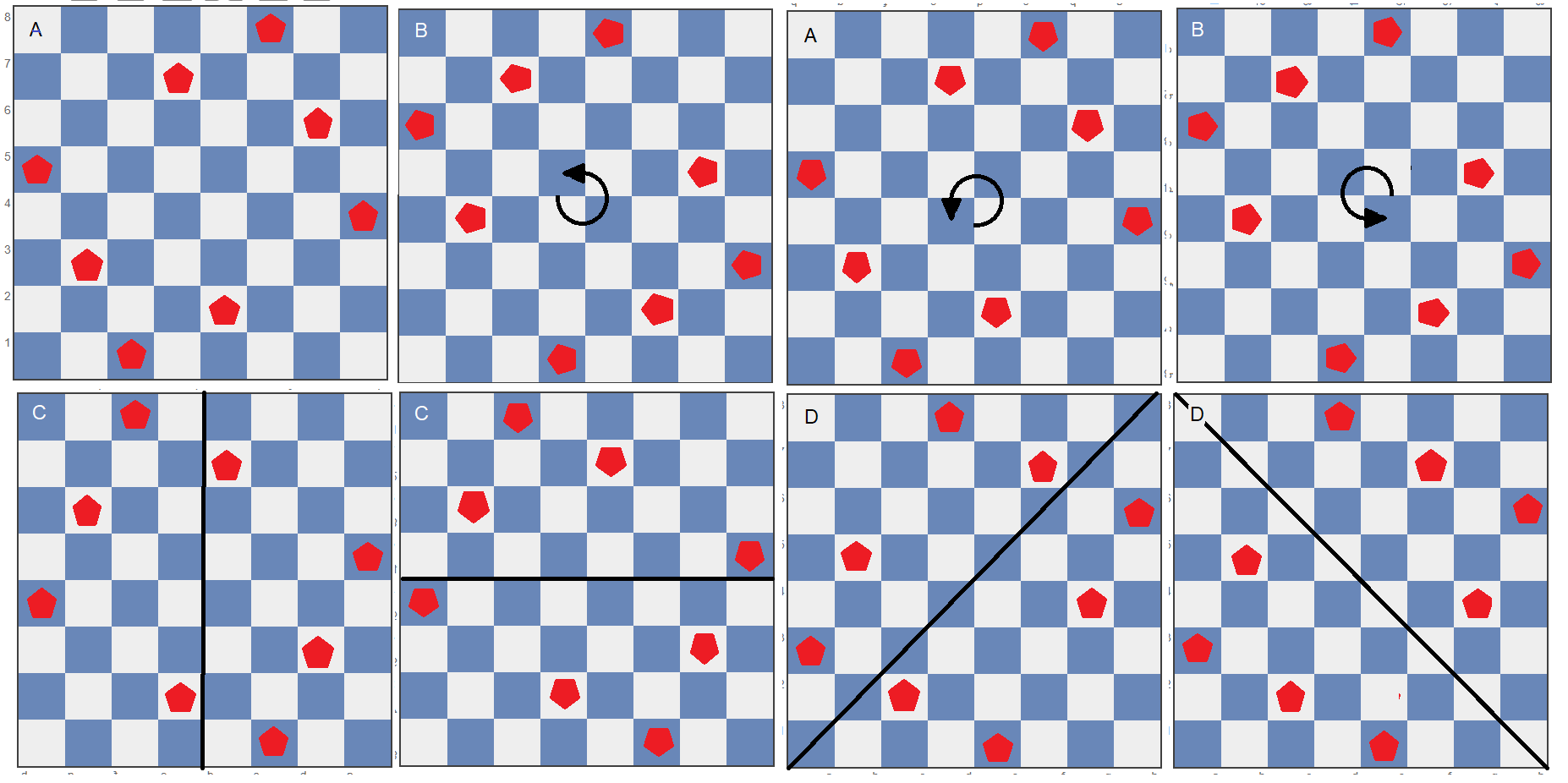
The eight queens puzzle is the problem of placing eight chess queens on an 8×8 chessboard so that no two queens can capture each other; thus, a solution requires that no two queens share the same row, column, or diagonal.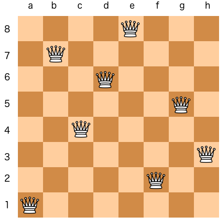 There are 92 solutions. Any given solution can be rotated 3 times and mirrored 4 times. That gives 8 solutions in total, so you would expected a final number of solution that is divisible by 8. The reason there are 92 solution and not 96 is that some rotations and mirrors are identical as showing in the picture below.
#!/usr/bin/python

import sys

#----------------------------------------------
def check_pos():
    global curr_row, curr_col
    # check cols downward
    row=curr_row - 1
    while (row > -1):
        if (queens[row] == curr_col):
            return False
        row -= 1
    # check diagonal left
    row=curr_row - 1
    col=curr_col - 1
    while (row > -1 and col > -1):
        if (queens[row] == col):
            return False
        row -= 1
        col -= 1
    # check diagonal right
    row=curr_row - 1
    col=curr_col + 1
    while (row > -1 and col < 8):
        if (queens[row] == col):
            return False
        row -= 1
        col += 1

    return True
#-----------------------------------------------
def backtrack():
    global curr_row, curr_col
    queens[curr_row]=0
    if (curr_row == 0):
        exit()
    curr_row -= 1
    curr_col=queens[curr_row]
    curr_col += 1
    if (curr_col > 7):
        backtrack()
    queens[curr_row]=curr_col
#----------------------------------------------
def print_solution():
    global solution
    print "    1 2 3 4 5 6 7 8"
    for row in reversed(range(8)):
        print row+1," ",
        for col in range(8):
            if (queens[row] == col):
                sys.stdout.write("|Q")
            else:
                sys.stdout.write("| ")
        sys.stdout.write("|\n")
    solution += 1
    print "solution ", solution, "\n"
#------------MAIN----------------------------------

queens=[0 for x in range(8)]

curr_row=1
curr_col=0
solution=0

while (True):
    if (check_pos() == False):
        curr_col += 1
        if (curr_col > 7):
	    backtrack()
        queens[curr_row]=curr_col
    else:  # check_pos returns true
        curr_row += 1
        if (curr_row > 7):
            print_solution()
            curr_row=7
	    backtrack()
	curr_col=queens[curr_row]
Permutations in C using backtrack()
There are a few different approaches in C with or without recursion to generate unique permuations of a string or array. The following example uses the same design as the 8 queens problem with checking and backtracking.
#include <stdio.h>
#include <stdlib.h>

  int n=5;

void print(char *array) {
  for (int i=0; i < n; i++) {
       printf("%d", array[i]);
  }
  printf("\n");
}

void backtrack(int *p, int *v, char *array) {

  array[*p]= 0;  // set back to start postition
  if (*p == 0) exit(1);
  (*p)--;
  *v=array[*p];
  (*v)++;
  if (*v > (n-1))  backtrack(p,v,array);
  array[*p]=*v;
}

int check(int p, int v, char *array) {
// checking for identical values in one row
// from right to left p--
 p--;
 while (p >= 0) {
   if (array[p] == v)  return 0; // not okay
   p--;
 }
 return 1;
}


int main(void) {

  char arr[5]={0};
  int pos=1;
  int val=1;

  arr[pos]=val;

  while (1) {
    if (check(pos, val, arr)) { // if okay advance pos
      pos++;
      if (pos > (n-1)) { // end of the line reached
          print(arr);
          pos--;
          backtrack(&pos, &val, arr);
      }
      val=arr[pos];
    } else { // advance val
        val++;
        if (val > (n-1)) backtrack(&pos, &val, arr);
        arr[pos]=val;
    }
  }
  return 0;

}
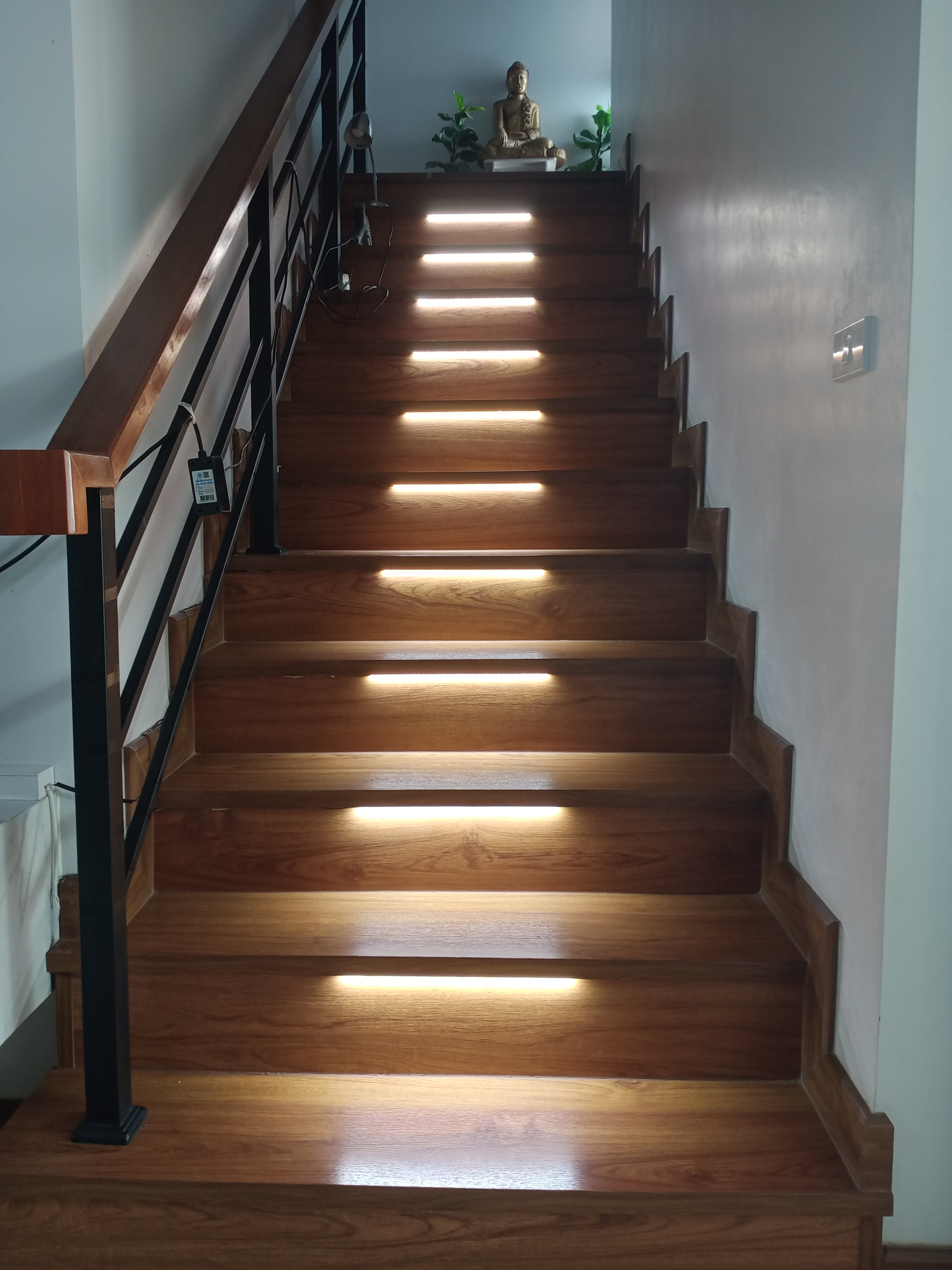
Staircase lights with 555 timer
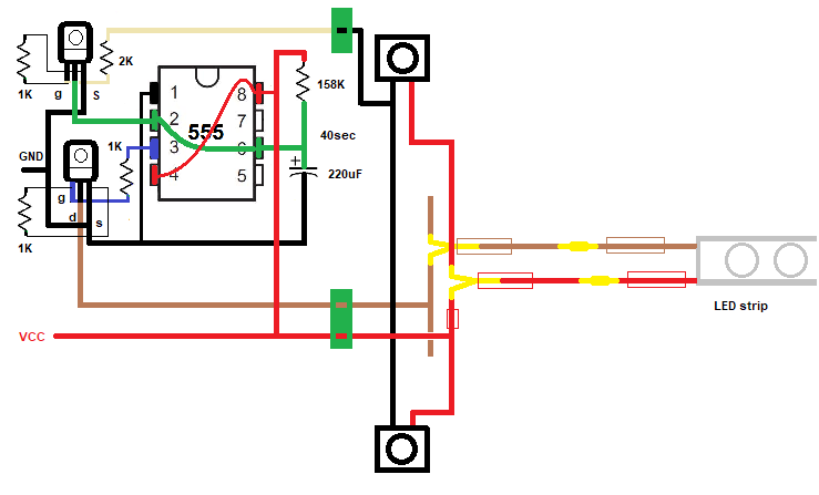 If one of the buttons is pressed timing of 40 sec starts again. Trigger and threshold are pulled down, discharing the capacitor and starts the charging from the beginning. Resistors of 1K between gate and source of the mosfet together with 2k to gate works fine; 10k and 11k resulted in a spontaneous turn-on after 2.5 hours.
Monostable 555 with touch plate
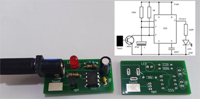 Classic monostable 555 with touch plate connected to the base of a NPN transistor. The pullup resistor of pin 2 is 1M ohm. Increasing the voltage helps the sensitivity of the plate, but I wanted to stick to 5 volt, because its availability. A better design would be with 2 plates with one to the base and the other one to Vcc.
Program Attiny85 using Arduino Uno

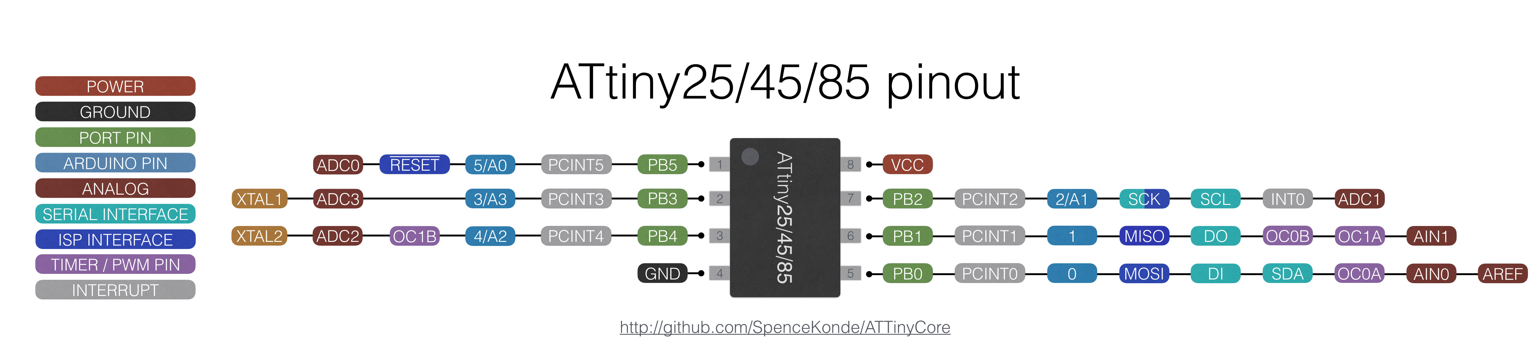
https://raw.githubusercontent.com/damellis/attiny/ide-1.6.x-boards-manager/package_damellis_attiny_index.json
1: Uncomment the #define USE_OLD_STYLE_WIRING in the ArduinoISP sketch!!!!!
2: Remove the 10uF capacitor when uploading the ISP sketch.
After uploading a sketch with an external clock (16 or 20Mhz) and you want to go back to an internal clock you have to attach the crystal when uploading the next sketch or you get an Device signature = 0xff00ff error.
Silhouette game with Arduino and Oled 128x64
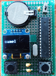
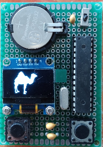
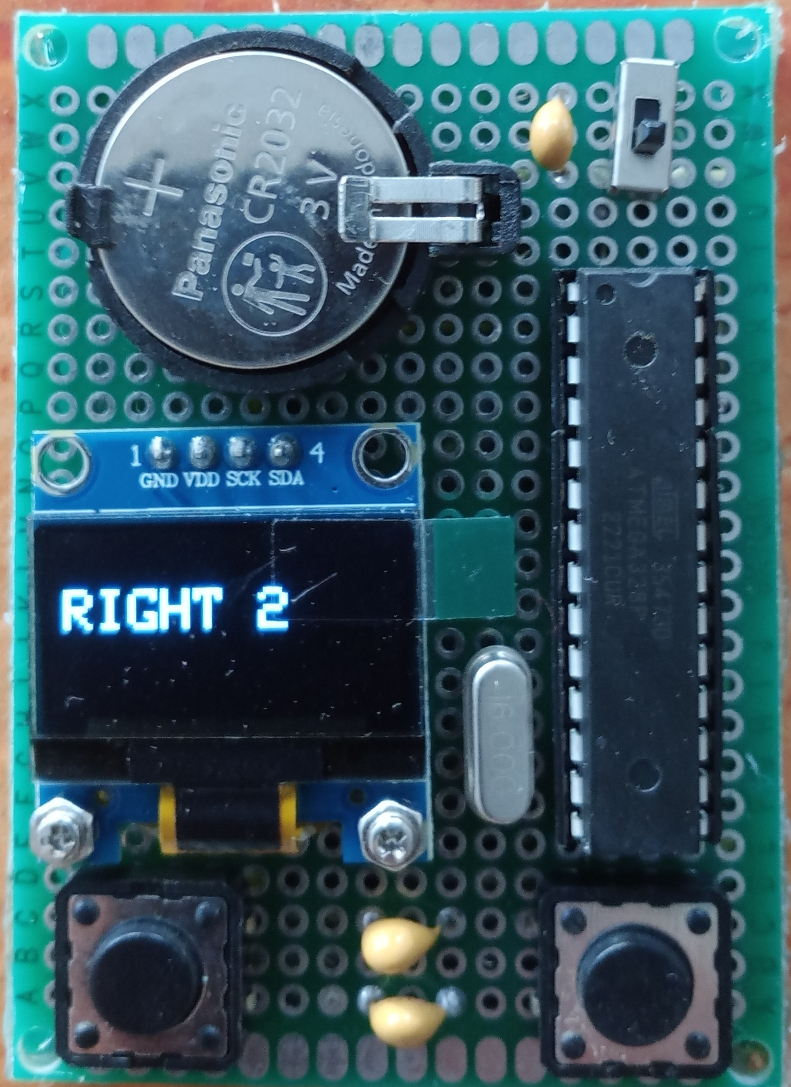 Switch the game on, read the name of the animal, when ready press left button and silhouettes of animals appear in succsession. Press right button when the
silhouette of the animal you've just read shows up. When correct you will see a the text "right" and the number of correct choices until now. When incorrect the text "wrong" with the number of incorrect choices is displayed.
Switch the game on, read the name of the animal, when ready press left button and silhouettes of animals appear in succsession. Press right button when the
silhouette of the animal you've just read shows up. When correct you will see a the text "right" and the number of correct choices until now. When incorrect the text "wrong" with the number of incorrect choices is displayed.After a short delay the game starts again.
>>> silhouette game code <<<